Friday, May 20, 2011

Civic Energy Suspension Engine Mount Inserts

I modified my Civic. I realise this puts me in a category known as 'chav' with some people, but my girlfriend can just deal with that!

The Civic is a bit of an enigma. It is a car that nearly develops 100bhp/liter in standard form without forced induction. It has stiff suspension, very stiff tyres and a close ration 6-speed gearbox. It seems like a car without too much in the way of compromise, with performance being at the forefront of most design decision. This is not the case and perhaps the most surprising compromise is with the engine mounts.

The engine / gearbox assembly is connected to the chassis via 4 mounts; nearside, offside, front and rear. The front and rear resist the rotational movement of the engine, an important consideration for a high-revving engine. It is these engine mounts that surprise. They are really soft!

Anyone who has owned and driven one of these cars will probably know about the wheel-hop issue. In the wet, accelerating in second gear is exciting. Traction is fine until you hit 5.8k revs, when Vtec kicks in. When this happens, the wheels lose traction and begin 'hopping'. What actually happens is that the engine is rotating clockwise and anti-clockwise, due to insufficient damping by the engine mounts, and traction is lost.

The solution to this problem is cheap. Energy Suspension produce so-called 'engine-mount inserts' which are polyurethane 'chunks' shaped to fill the gaps in the standard mounts. These increase the stiffness of the front and rear engine mounts, and really do prevent this wheel-hop in the wet.

Removing this compromise does actually go some way to explaining why Honda designed the car in this way in the first place. The stiff engine mounts cause significantly increased vibrations within the car, especially when idling. This appeared very bad initially and has reduced since fitment. Whether this is softening of the mounts over time, or I'm becoming accustomed to the vibrations, or both, I don't know. However the vibration issue is easy to live with due to the much-improved gear changes.

With a stiff mounted engine, blipping the throttle on downchanges has become a joy. The car feels much more like a Type R should be: informative, responsive and satisfying to drive. It is hard to drive smoothly compared to a normal car, even moreso after this modification, but it can be driven smoothly with a lot of driver involvement. I am constantly trying to better myself as a driver and having a car that lets me know if I'm doing the right things or not means that even driving smoothly around town is a satisfying experience. This car is not for everyone but at this stage in my life, I absolutely love every minute.

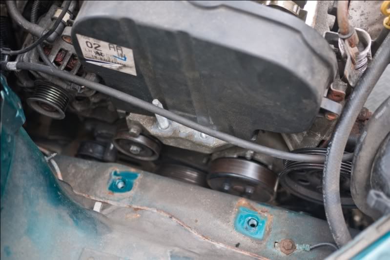
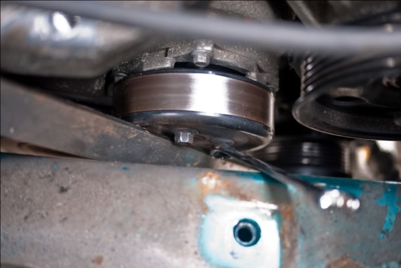
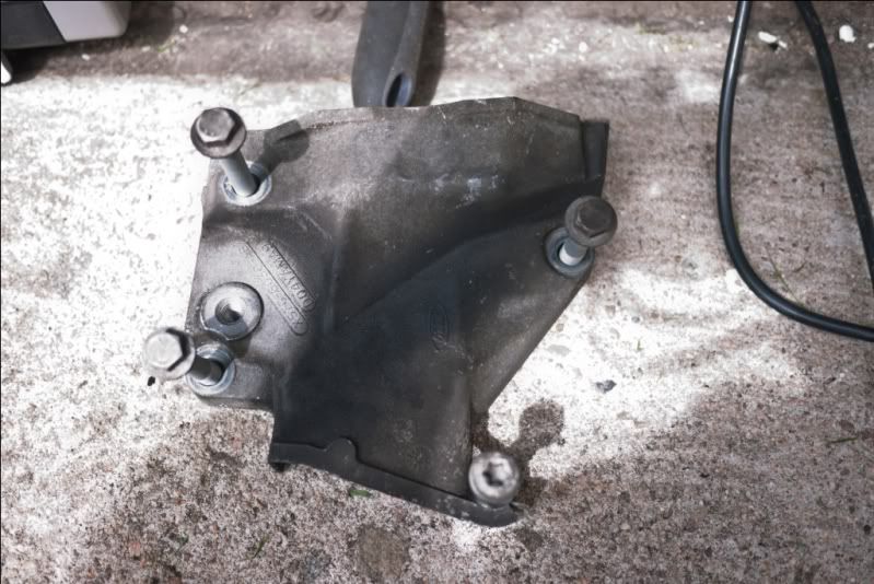
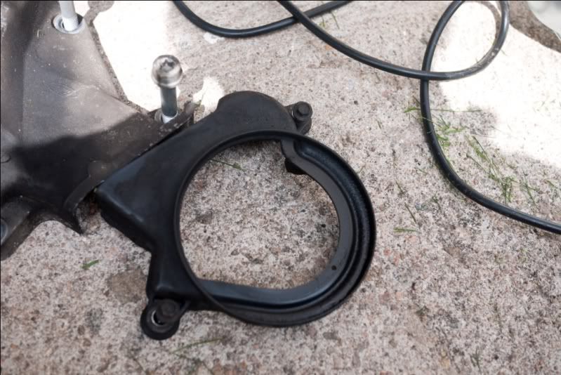
Fitting these was difficult because it required the subframe to be dropped down. I didn't take any under-car pictures but I did take some pictures of the mounts when removed from the car.

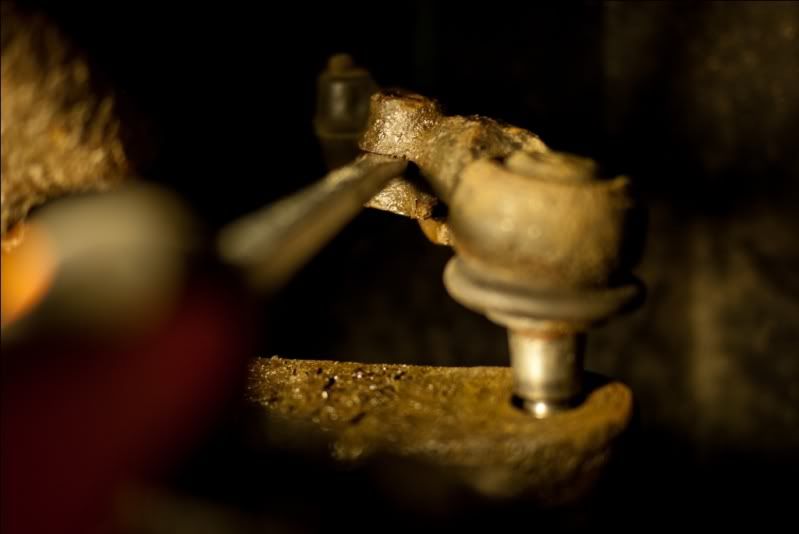
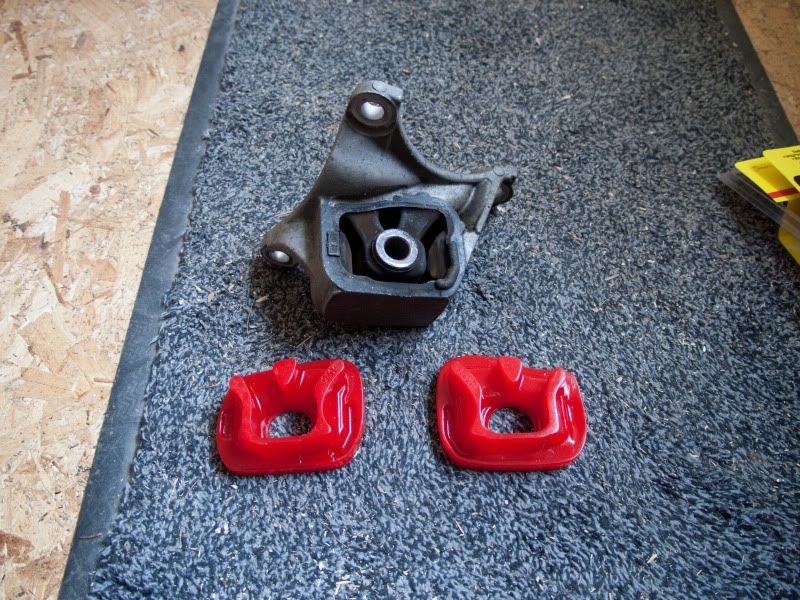
One of the mounts showing the gaps all around the mount.
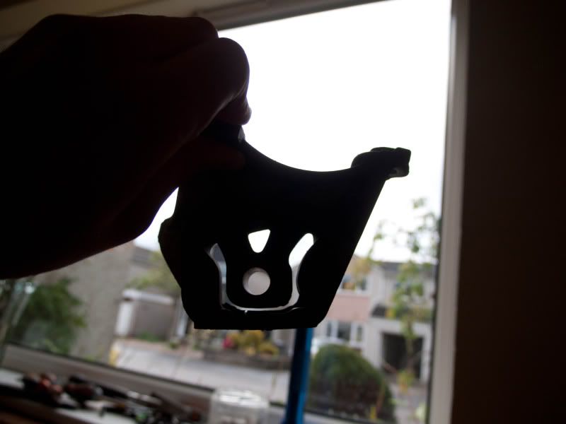

The inserts for this mount.

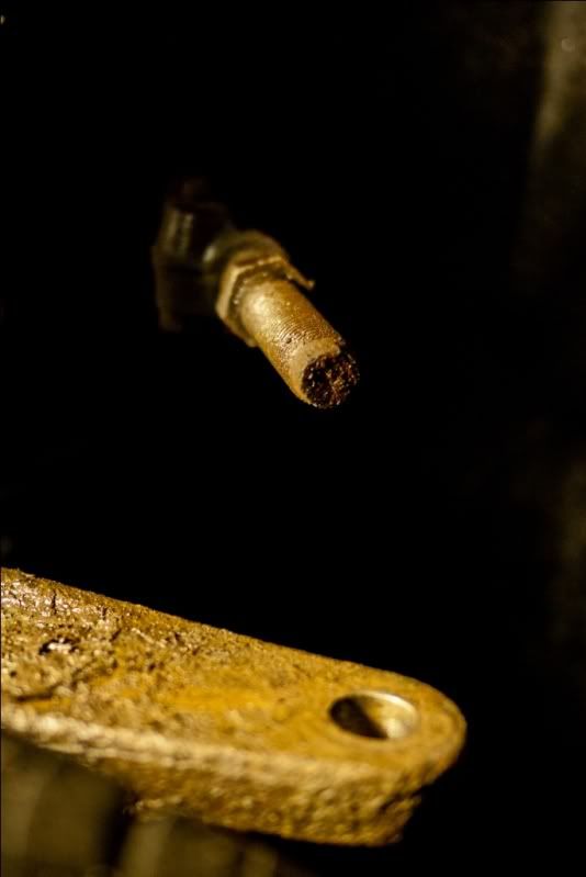
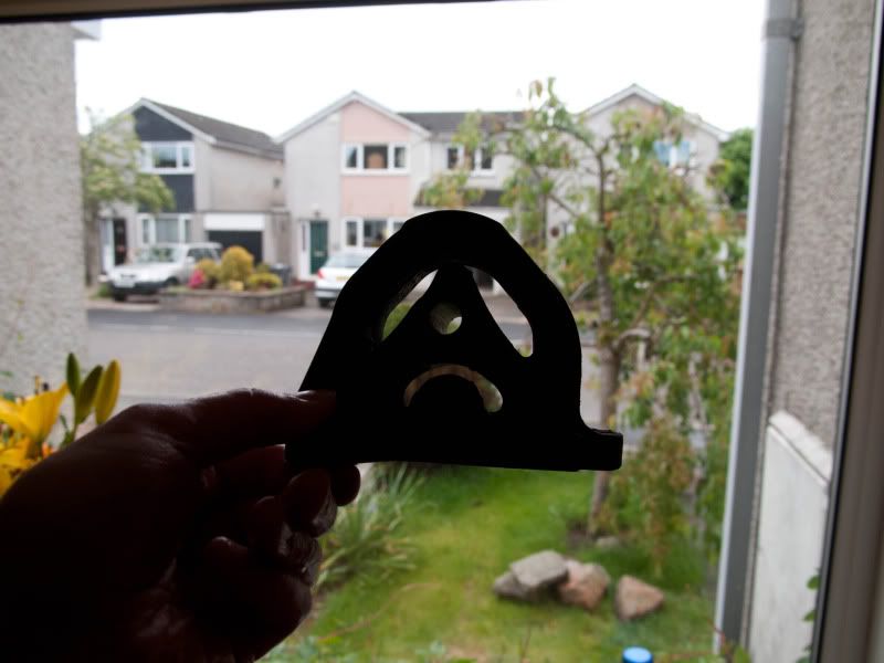
The other mount. Mount is sad.

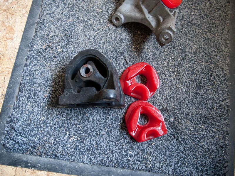
Again, picture showing inserts.

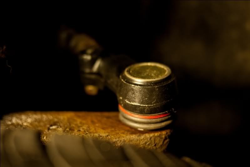
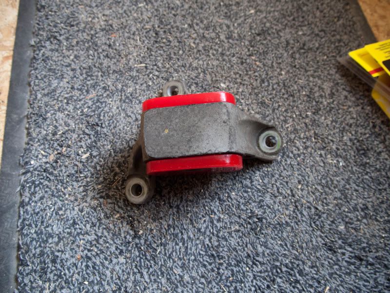
How the mount looks with the inserts fitted.
Thursday, December 30, 2010

Freelander Oil Cooler Pipe Rupture

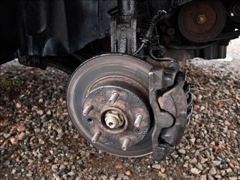
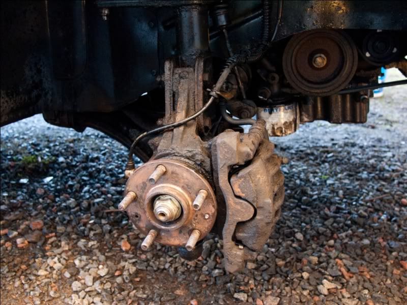
The missus came home from work yesterday complaining that the oil light on the dash was 'flickering'. I went out to look and the front drivers side wheel was covered in engine oil. I pointed this out and she corrected me; "No, that's just road grime."

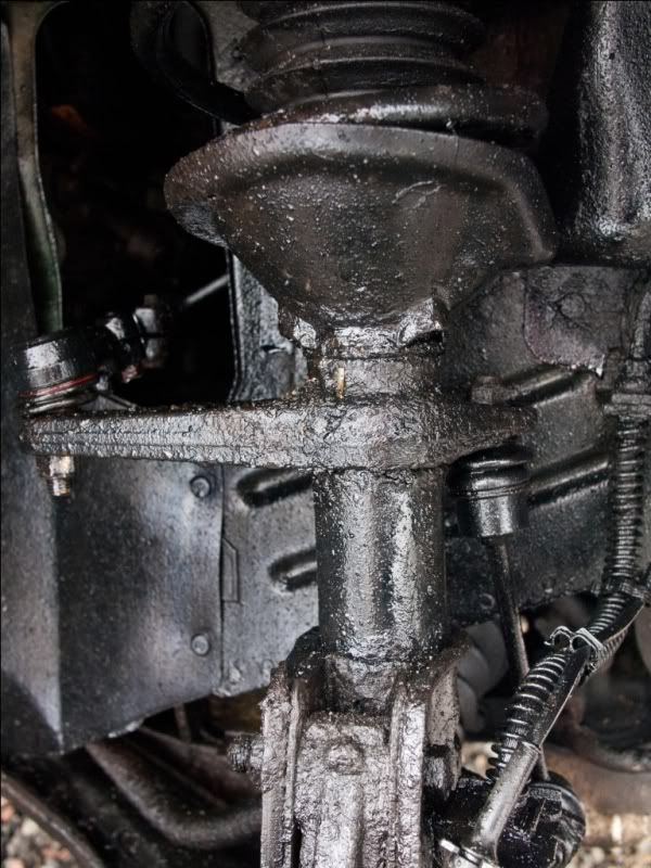
Well upon closer inspection, it appears that this 'road grime' has come from a corroded oil cooler pipe which just so happened to spring a leak that sprayed the entire front hub in oil!

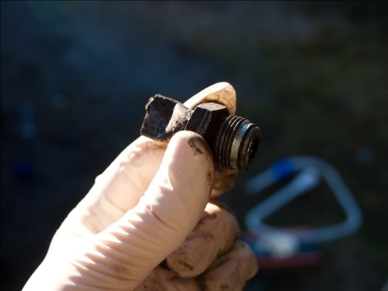
Here's the slimy remnants:


I have ordered new pipes, new front discs and pads, new oil filter and new oil. I'm not going to enjoy getting messy with this one, I just know it.


Update 1 (31/12/10)

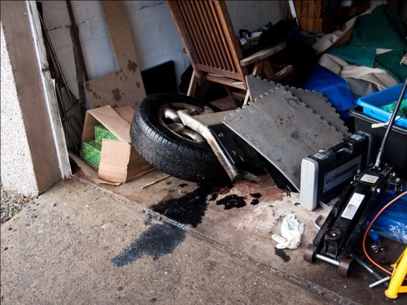
I managed to get the removal work done today. I multi-tasked by draining the oil, then soaking the messy drivers side hub with degreaser whilst setting about removing the passengers side brakes.

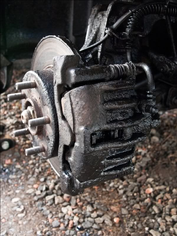
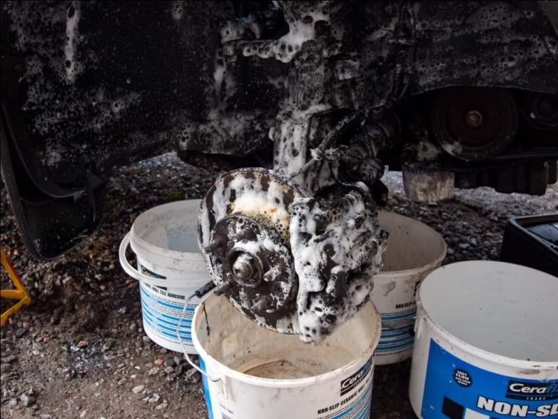
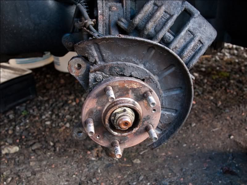
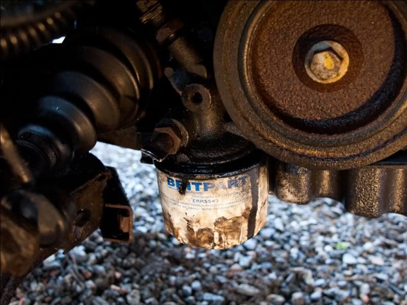
Here's a picture of the oily side soaking with some degreaser that had a lovely citrus smell!!


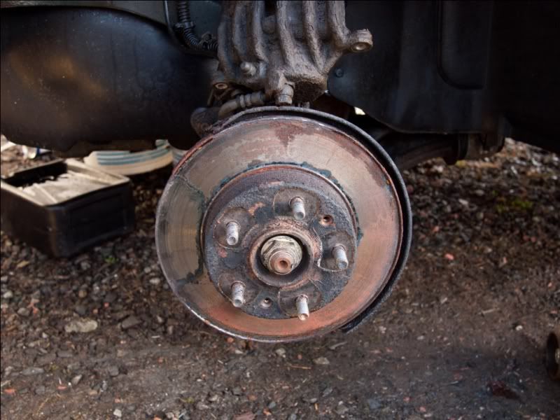
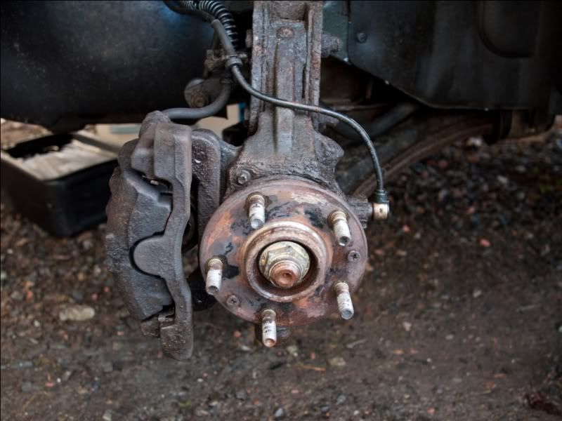
Passenger side hub with caliper removed. This was incredibly difficult to remove partly due to the wear lip on the edge of the disc and partly because the car is old and everything was very tight.


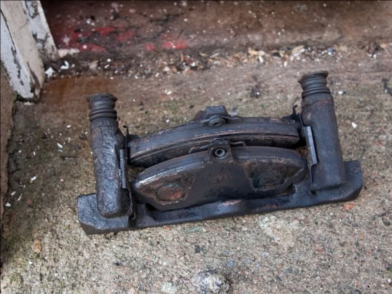
Old pads.


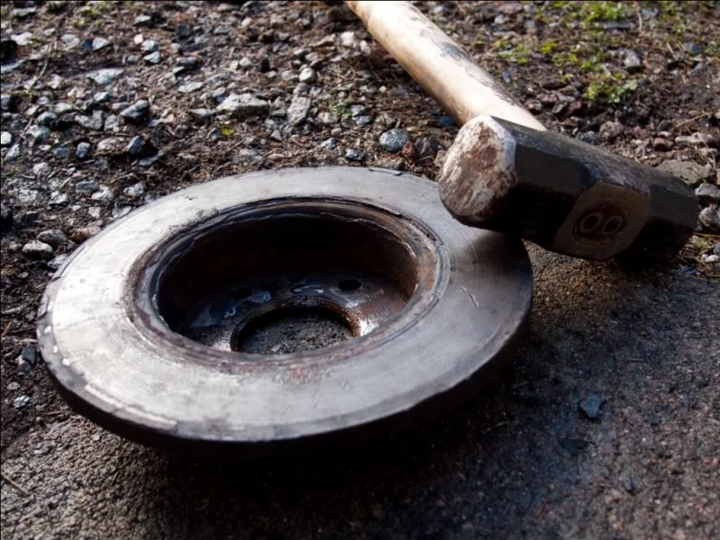
The old disc proved very reluctant to budge. I had to resort to violence and even then it took a good 5 minutes.


The dust cover was badly corroded and had to go.


Having cleaned everything, I reassemble whilst I'm waiting on parts arriving in the post.


I then repeated the procedure on the drivers side. This was more difficult as two bolts holding the caliper in place had rounded off. I had little option but to take a slightly smaller imperial socket and fit it over the rounded bolt using the sledgehammer. Luckily they both came free and I managed to clean things up and put it back together again. I left the imperial sockets in place for now.


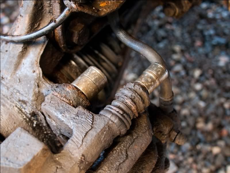
Now I removed the oil cooler pipes. These were very stiff too. Once removed I cut the ends off, crimped them then put them back in place to stop any debris getting into the oil system.


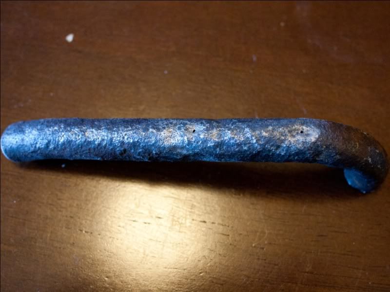
And finally here's a shot of the offending piece of pipe with the two small holes clearly visible.

Sunday, December 19, 2010

Freelander Wiper Motor Bodge

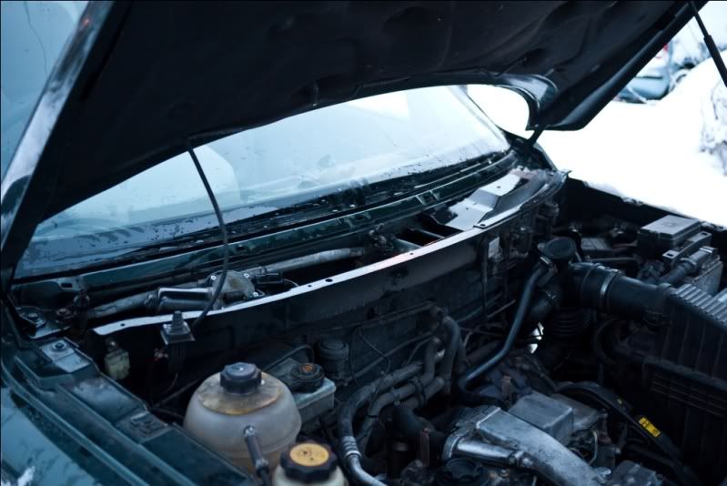
I'd recently cleaned a load of snow off the screen on my girlfriend's Freelander, and after this the wipers stopped working. I changed the fuse but it kept blowing. I disconnected the motor and this stopped the fuses blowing. The problem therefore had to be within the motor unit.

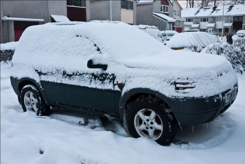
So...I went outside to find this had happened overnight...!


Once cleaned off, I started taking things apart. Once the scuttle was removed, I could see the motor assembly. At this point I disconnected the plug and tested the circuit - no fuse was blowing which showed the problem was within the motor unit.


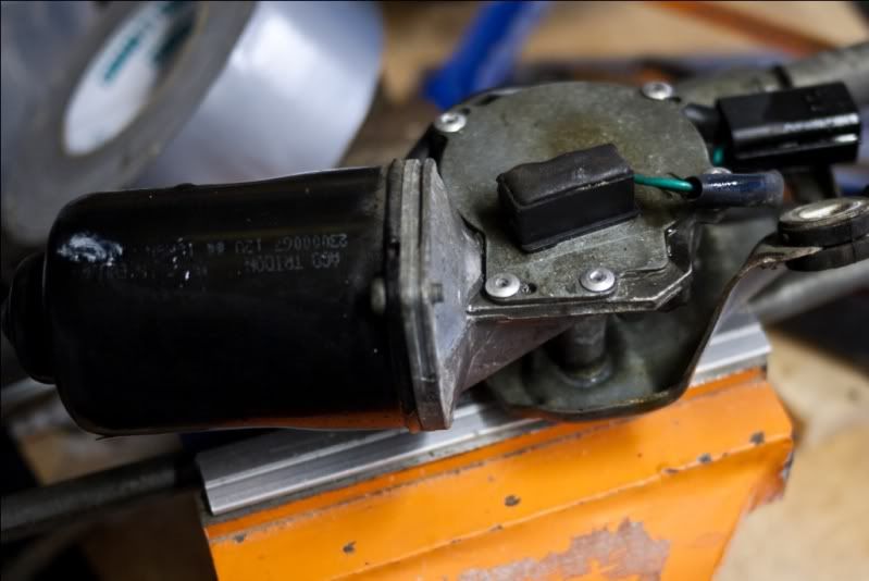
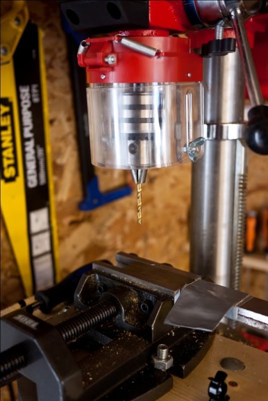
I removed the motor assembly and took it to my workshop. I drilled out the rivets and opened the gearbox.


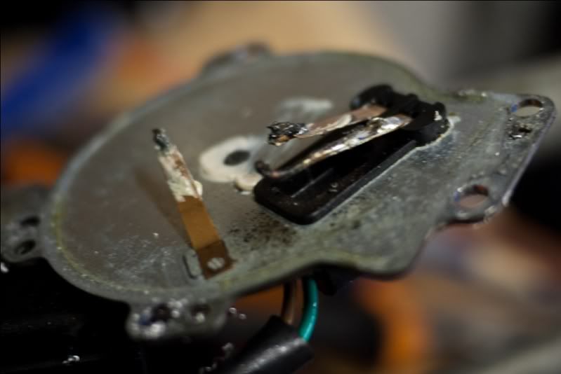
Aha! My previous solder job had melted and repositioned itself under high current load whilst shifting heavy snow.


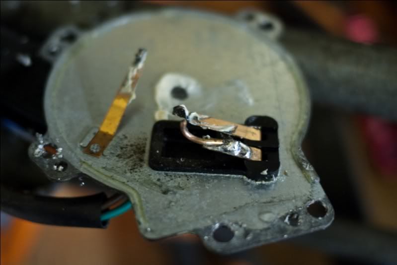
I got the soldering iron out and put it back where it should be. This is not ideal, but as the car is on its last legs, and I promise not to use the wipers in an aggressive fashion again, it should hopefully suffice.


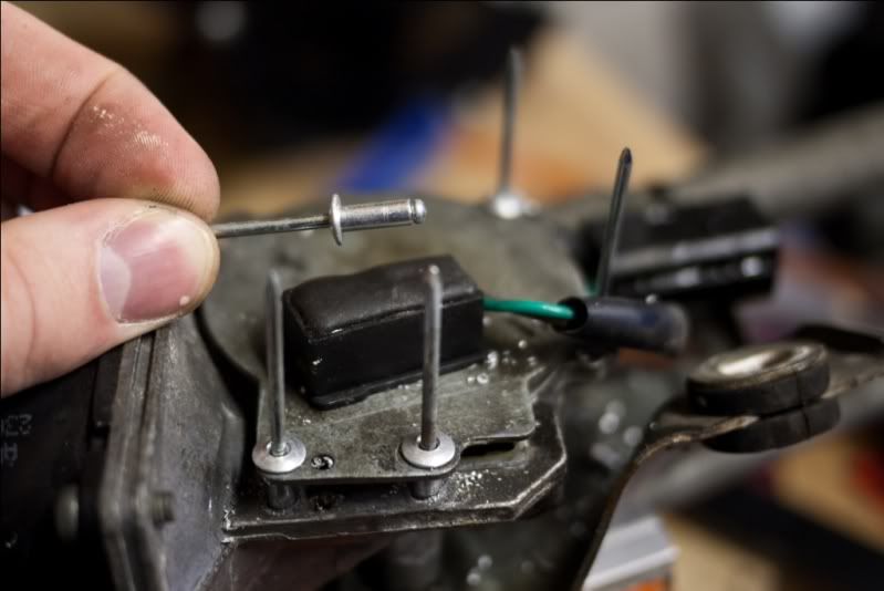
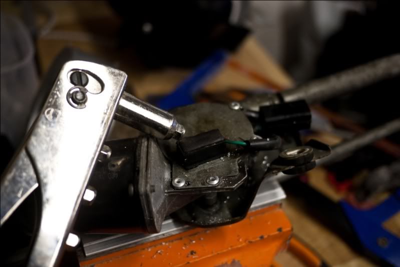
Put cover back, rivet in place.


Reinstall, put everything back and test. I don't know if the movement comes across in this photo but it all works as it should do now.

Tuesday, December 14, 2010

Freelander Track Rod End Replacement

This winter has already taken its toll on my girlfriend's Freelander. Lots of clunking and a wobbly wheel led to the discovery of a borked track rod end. I got a replacement today so took a few pics whilst changing it.

Unfortunately my girlfriend is in Brazil and I could NOT find the locking wheel nut key ANYWHERE! So, I had to leave the wheel on and fumble about like a cock!

Here's the old one:


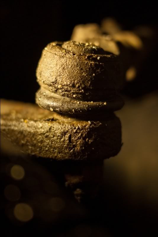
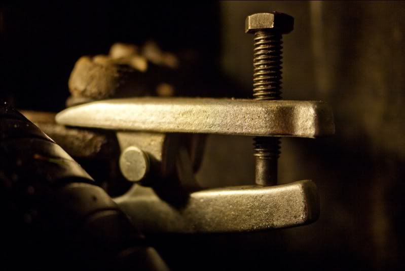
Removed the bottom nut, and used my trusty ball joint splitter to make a lovely clunk noise.


Once loose, I had to remove the clamping bolt - an unusual feature that I've not seen on a track rod end before. Using a screwdriver to loosen the assembly. Once loose, it simply unscrewed. Well, it was damn tight but it came eventually! I counted the number of turns it took to come off.


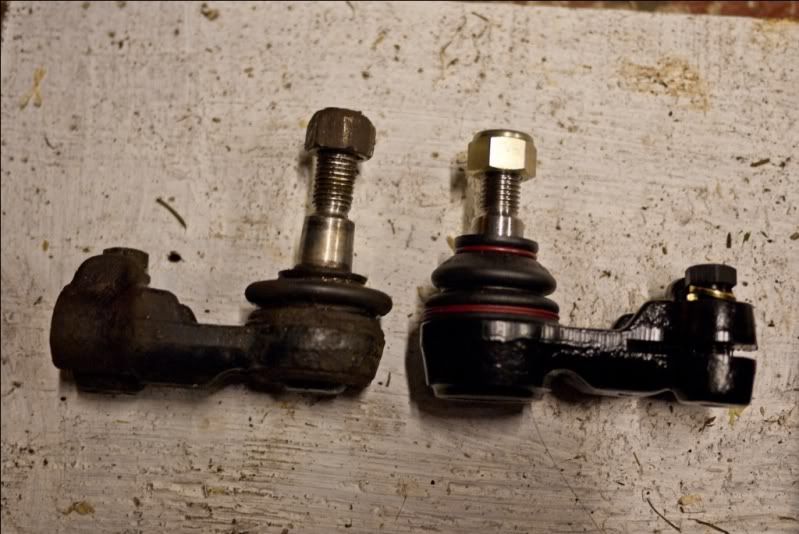
Here's the obligatory old vs new shot.


Clean up the hub and track rod.


Fit the new one turning it the same number of turns that the old one had.


Got the car booked in to get the tracking done now. I'm concerned there's something else wrong with it as it's still making funny noises, but these cars are notoriously unreliable and this is a 12 yr old example....

Sunday, July 25, 2010

Ford Focus Timing Belt Replacement (1.8 Zetec)

Well today I changed the timing belt. Been meaning to do it for some time now, it's done 9 odd yrs service and 80000 miles or so. Still within the Ford replacement period, I decided sooner rather than later...

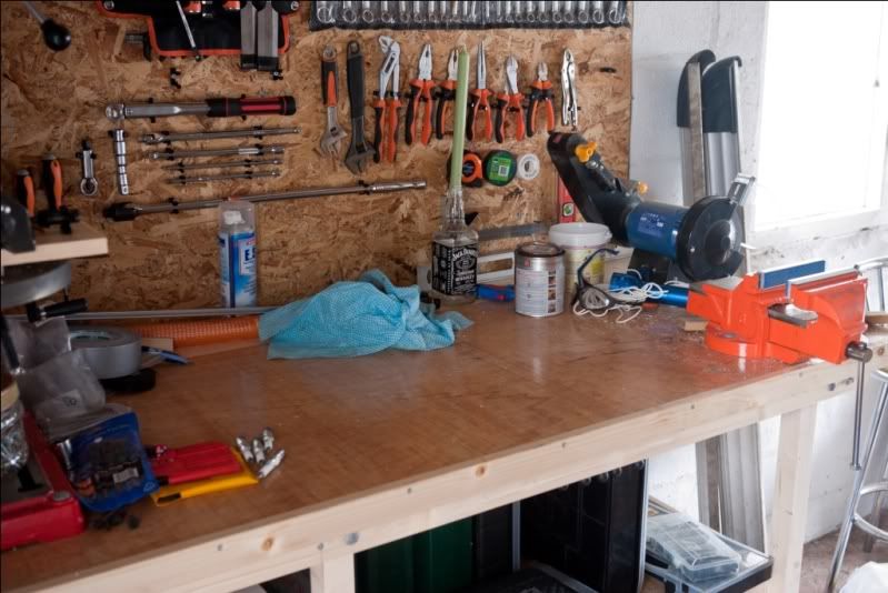
First of all, clear some work space....


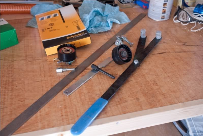
Get all the things you need together. New belt, idler and tensioner pulleys, and some other gubbins.


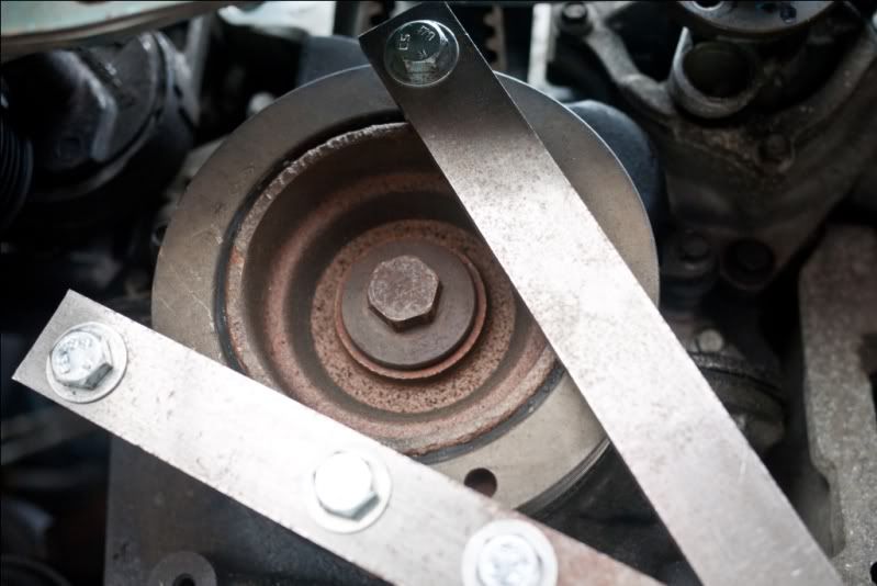
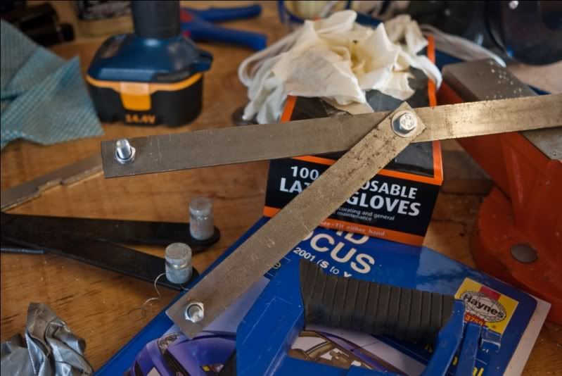
First job was to make a crankshaft removal tool. Get some steel bar, and cut a bit off the end. Grind the ends to remove sharp edges, tape together and drill.


Voila, one crankshaft removal tool, or so I thought.... It required a bit of modification later on.


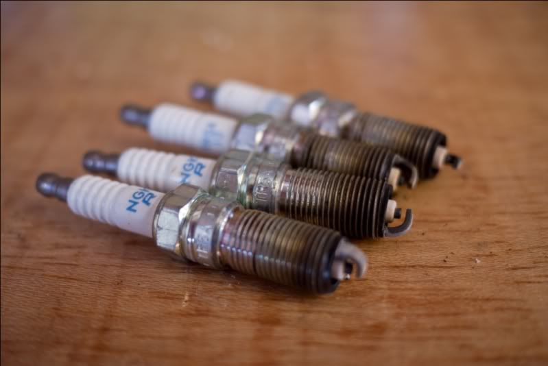
Right, now jack the car up and get it on axle stands. Remove the front wheels and remove the offside wheel arch lines. Remove the spark plugs and store away safely.


Remove the camshaft cover and store away safely.


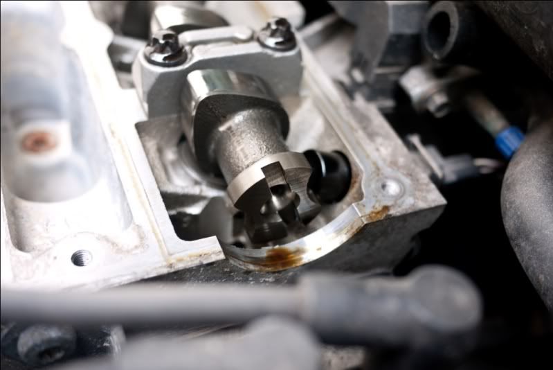
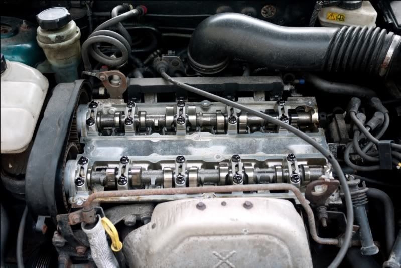
Now, look at the ends of the camshafts. They are slotted.

Using an 18mm socket on the crankshaft, slowly turn the crankshaft until the camshaft slots line up with the machined flat surface on the head.


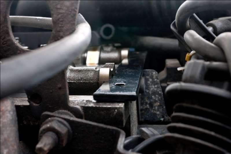
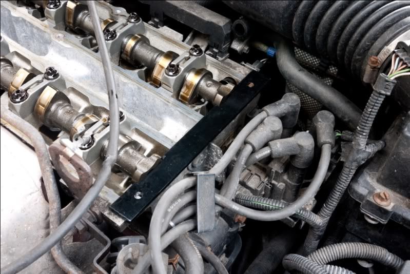
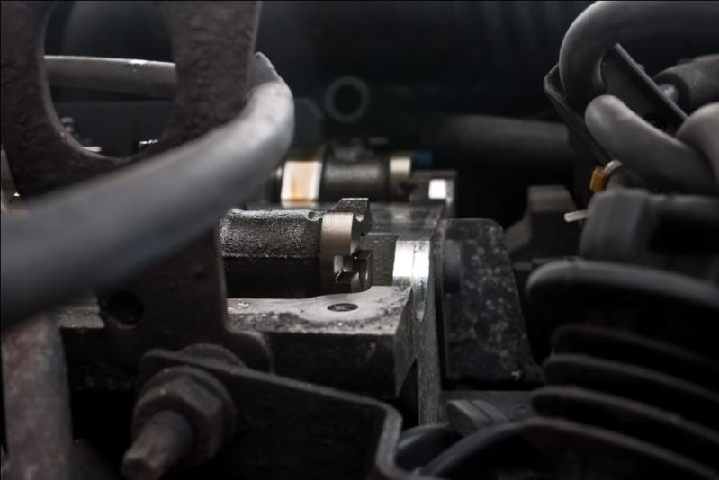
What we're looking to do is find Top Dead Centre (TDC) for the nearside cylinder. The camshaft locking tool should slip into the slots as shown below. This can be quite fiddly.


This is how the camshaft should look. It can also be 180° out of sync, with the nearside inlet valve having just closed rather than about to open as shown in the picture. Turn the crankshaft again until they are lined up as shown.


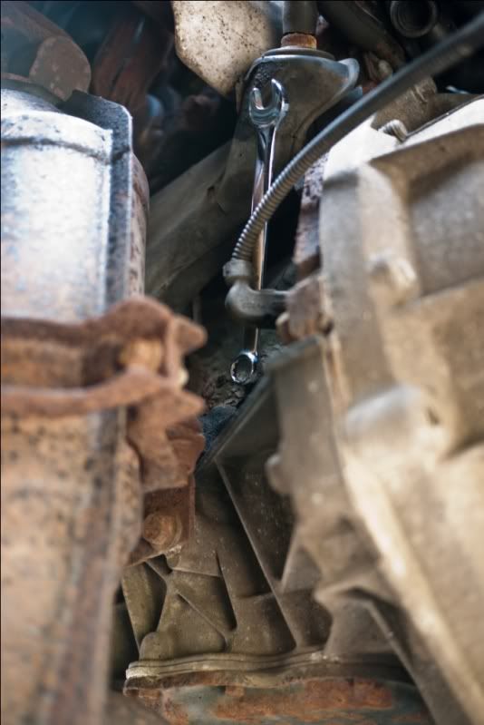
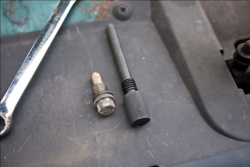
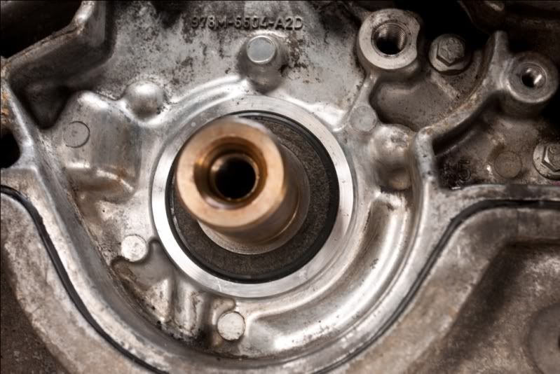
Next we install the crankshaft locking pin. This is awkward to get to, as it's behind the CAT. A 10mm spanner as shown will undo the blank, which should be removed and stored safely.


Blank and locking pin side by side.


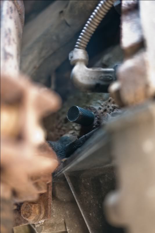
Locking pin installed. Now the crank can be rotated slowly clockwise until it comes into contact with the pin. This is TDC, and it is the crank pin which you must go off for verification.

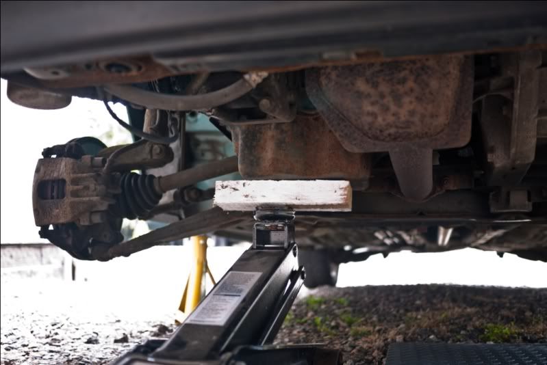
Next, remove the auxiliary drive belt cover, drive belt, etc. Jack up the sump with a block of wood between the jack and the sump.


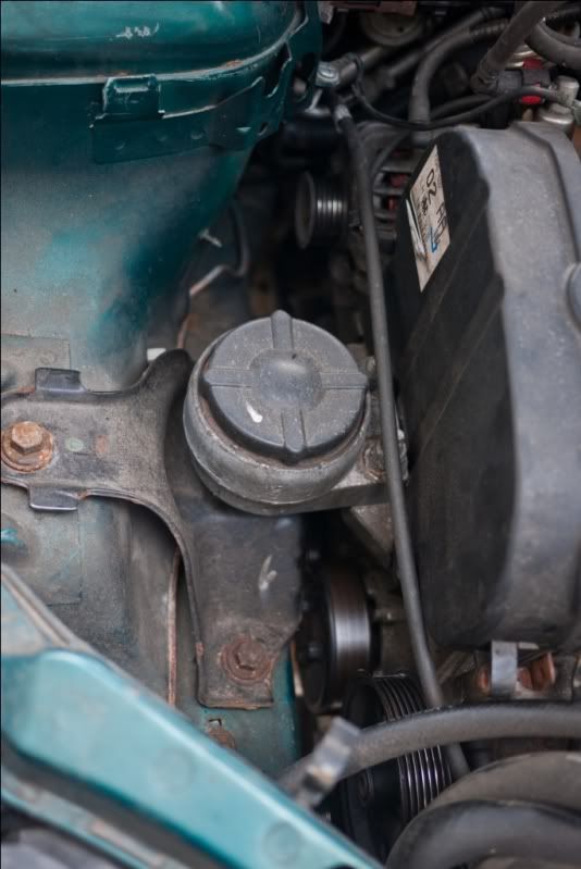
Loosen the bolts holding the offside engine mount to the car. Take a picture of how this is located, as you'll want to put it back as close to where it came off as possible.


Undo all the bolts, including the ones on the engine side and remove the mount. Be cautious as the engine is now resting on the jack.


I cocked up here. I should've loosed the coolant pulley bolts with the auxiliary drive belt still on. Never mind, use a wedging device (steel bar!) to hold it still whilst you undo the bolts with a 10mm spanner.


Once that and the aux belt idler pulley have been removed (you'll need to keep adjusting the height of the engine with the jack for access), remove the 4 bolts holding the middle timing belt cover in place, and remove it.


Now using the modified crankshaft tool, hold the crank still whilst you loosen and remove the pulley. If we didn't use the tool, it might shear the crank locking pin which isn't terribly desireable.


Once removed, you can remove the lower timing belt cover.


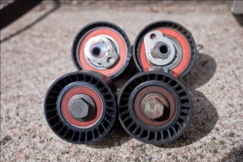
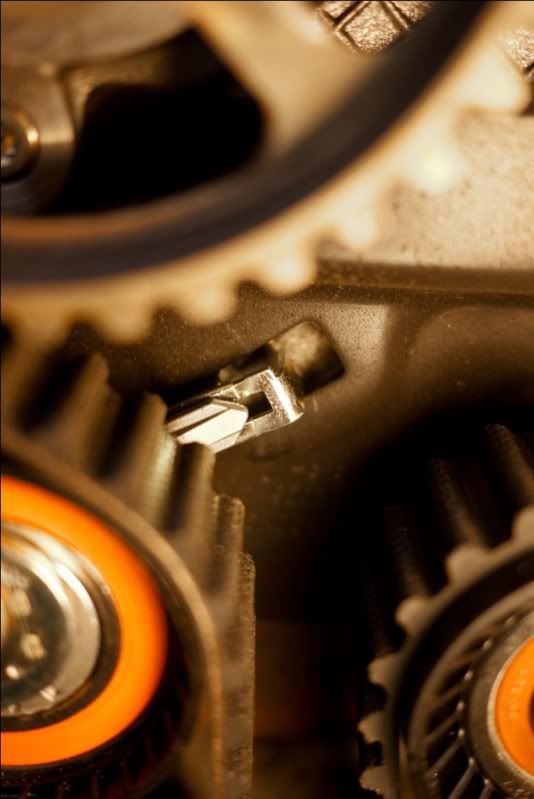
Now release the tension on the timing belt and remove the idler and tensioner pulleys. Here's old plus new - all appears to be the same shape which is a good thing!


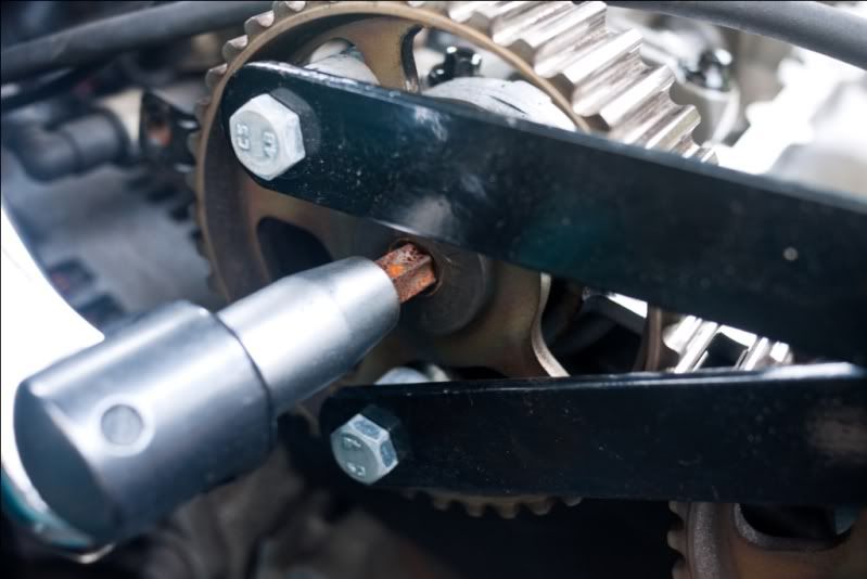
Next loosen the crankshaft sprockets using a proper tool!


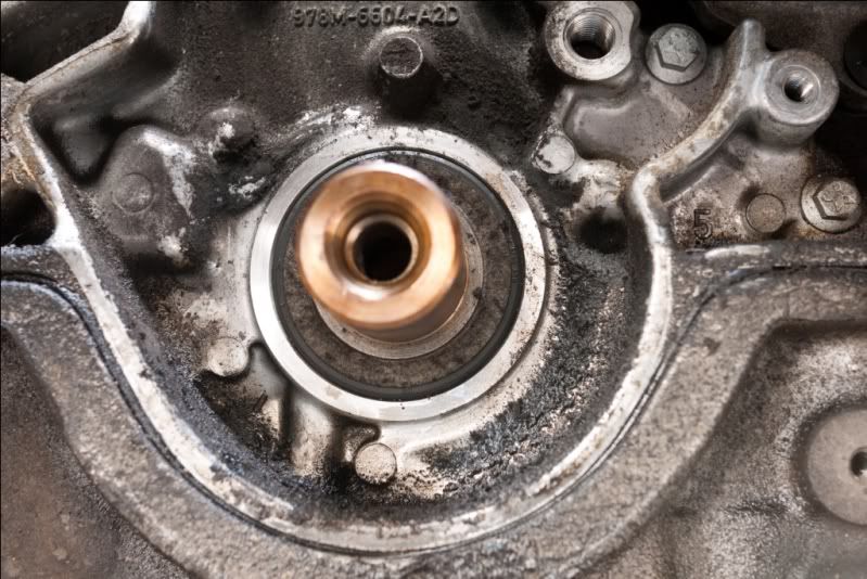
Give the manky bits a clean - this is an ideal opportunity to spot any troublesome leaks and do something about it,


Putting it all back together shouldn't be too tough once you've come this far. When tensioning the belt, use an allen key to align the arrow with the locking tab.


Right, now set the timing using the crankshaft locking pin and the camshaft locking bar. Once set, remove both locking devices and rotate the crank 2 turns using a wrench. This seats the belt afterwhich you must re-check the timing. If it's out, make adjustments and give it 2 turns again. Keep going and be patient, you will get there!

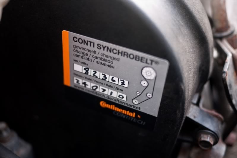
Once it's all together, stick a sticker on showing when it was replaced for future records, then take it for a test drive.